Quick answer
What makes two pressure-drop values comparable?
Keep each value with the airflow or velocity, area used to define that velocity, specimen construction and test condition. Separate clean, initial resistance from a loaded or final value. Do not compare a flat media sample with a complete filter as if they were the same test item.
For example, Freudenberg's product data lists nominal airflow, face velocity, initial pressure drop and recommended final resistance as separate fields. That is a useful documentation pattern, not a specification for Junkang media.
How to calculate filter face velocity from airflow
For a stated frontal reference area, the average velocity is the volume flow rate divided by that area. Keep the units consistent:
v (m/s) = Q (m³/s) ÷ A (m²)
v (m/s) = Q (m³/h) ÷ [3,600 × A (m²)]
Q is the airflow through the filter under review. A is the frontal area used for the calculation, not the total surface area of pleated media.
The U.S. Department of Energy's Building America guide explains the flow–velocity–area relationship for ventilation measurements. Applying that relationship here gives an average approach velocity; it does not prove that local airflow is uniform or establish an acceptable operating speed.
Worked example: the same airflow, two frontal areas
Illustrative calculation only—not a product size, test result or recommended velocity.
Assume 324 m³/h passes through an unobstructed 300 × 300 mm frontal area:
Q = 324 ÷ 3,600 = 0.09 m³/s
A = 0.3 × 0.3 = 0.09 m²
v = 0.09 ÷ 0.09 = 1.0 m/s
At the same flow, an assumed 600 × 600 mm frontal area is 0.36 m². Its calculated average velocity is 0.25 m/s.
This arithmetic does not predict either pressure drop. Ask for data at the relevant operating point. If a frame obstructs part of the opening, state which area the supplier uses. If several filters share the equipment airflow, record the airflow through the particular filter rather than assigning the full total to every panel.
Face velocity is not the same as media velocity
Face velocity describes the approach flow at the front of a filter. Media velocity concerns flow through the filtration material itself. In a pleated filter, the frontal area and the media surface area are different; local flow through the folds is not necessarily uniform.
A University of South Florida study of pleated air filtration makes this distinction and examines how pleat geometry affects local velocity. Do not use a complete filter's outer dimensions as its total media area, or assume that a flat-sample result establishes the performance of a pleated assembly.
Two quotation scenarios that need clarification
The figures below are invented examples to illustrate missing information. They are not Junkang test data.
Do not convert one resistance value using an assumed universal linear or square-law multiplier. Keep the actual curve, method and test conditions with the model reference.
What to request before approving a replacement
- Model and constructionIdentify the media, thickness, layer arrangement, support and any frame or pleats included in the test.
- Airflow and reference areaRequest the flow rate or velocity with units, the test dimensions and the area used to define the velocity.
- Pressure-drop dataAsk whether the result is initial or loaded, what the stated final resistance means, and whether data covers your operating point.
- Performance evidenceReview particle capture or target-gas performance separately. Low resistance alone does not establish either.
A pressure-drop check is not a complete system-design review. The equipment designer must also confirm the airflow requirement, available fan pressure and installation arrangement. For the distinction between particle ratings and gas-phase tests, use the test-report scope guide.
Use the same airflow discipline for carbon and white media
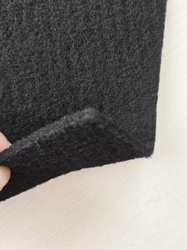
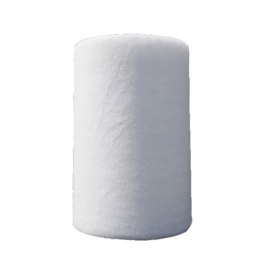
For carbon media, state the target gas or odor as well as the required airflow and construction. For a white pre-filter, state the required particle-filtration specification and installation position. Those are different performance questions, even when both stages are used in one assembly.
- PET-based activated carbon media: specifications and inquiry
- Other activated carbon material structures
- White synthetic pre-filter media: specifications and inquiry
- White pre-filter RFQ checklist
Send the existing datasheet, known airflow, dimensions and application through the relevant product inquiry form. If a value is unknown, identify the gap rather than inventing a rating or operating limit.
Frequently asked questions
How do you calculate filter face velocity in m/s?
Divide airflow in m³/s by the stated frontal reference area in m². If airflow is in m³/h, divide it by 3,600 first. State the area used and the airflow through that filter, rather than assuming the full equipment airflow passes through every panel.
Can I compare pressure-drop figures measured at different velocities?
Not by comparing the pressure numbers alone. Ask for results at the same velocity and comparable test conditions, or for a curve covering your operating point. Do not convert a single value using an assumed multiplier.
Does low pressure drop prove good odor removal?
No. Pressure drop describes resistance to airflow, not gas-removal performance. A carbon-media selection also needs evidence for the target gas and test conditions; a particle-filter rating does not supply that evidence.
Technical sources and scope
These references support the general airflow relationship, terminology and documentation principles. They are not tests or certificates for Junkang products. No competitor performance value is used as a Junkang specification.
- Building America Solution Center: Measuring Mechanical Ventilation Airflow—volume flow, average velocity and cross-sectional area.
- Schousboe, University of South Florida (2017): Media Velocity Considerations in Pleated Air Filtration—face versus media velocity and local flow in pleated geometry.
- Freudenberg Filtration Technologies: Compact T 60 product data—an example of reporting airflow and resistance conditions separately.
- ISO 10121-1 and ISO 10121-2—gas-phase media and complete-device test scopes.